|
|
|
||||||||
|
|
|
||||||||
![]()
| Punkin's Restoration - 1978 Spitfire | ||||||
|
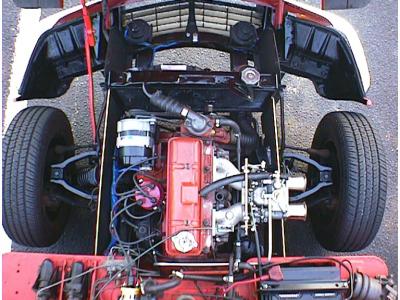
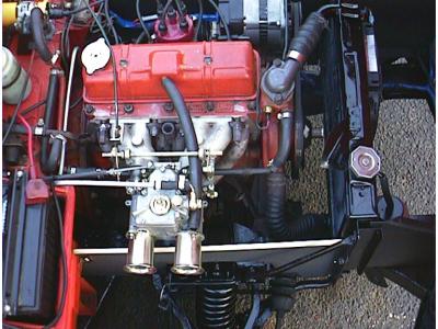
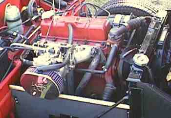
The engine has been balanced. It has a Kent mild road cam, Mallory Dual Point Distributor, and a single Weber DCOE 45 carburetor mounted on a Cannon manifold with vibration isolation mounts. The head has been shaved, and the pistons are flat top TR6 variety (+0.040" compared to stock Spitfire pistons). The compression is somewhere around 9.93:1. A compression test shows all cylinders up around 195 psi +/- 5psi. Tick-over is a bit rough, but that's attributed to the overlap in the cam timing and the higher that stock compression. At an idle speed of 925 rpm, she's fairly tolerable at a stop light.
Playing with the wiring (cleaning up the harness and routings) I busted the ballast resistor that was mounted on the bracket holding the Crane ignition coil. I swapped the system back to an un-ballasted system with an Accel 'Yellow Jacket' Coil. (Hey is was cheap, and available locally from the parts store down the road.) Spark plug gap has been opened up to 0.035". The mechanical advance of the Mallory dual point distributor has been adjusted to give a maximum of 28° advance. The idle timing at 925 rpm is set to 10°BTDC.
It's pretty wild to listen to an engine when the sound of the carburetor sucking air, is as loud if not louder than the Free Flow Exhaust note. It seems to rev very freely all the way up to and past the 7KRPM tach markings. On the road, she pulls like a freight train from 2500 all the way to 6500 rpm in third gear.
In the above photo you can see the engine valence panels I made up from masonite board (un-perforated peg board). The top edge trimming is actually gold colored wall-to-wall carpet floor rug edge trimming aluminum strips that have been cut and crimped to fit the board edges. They are painted with black Bar-B-Que grill high heat paint. Nice color contrast.. ay!
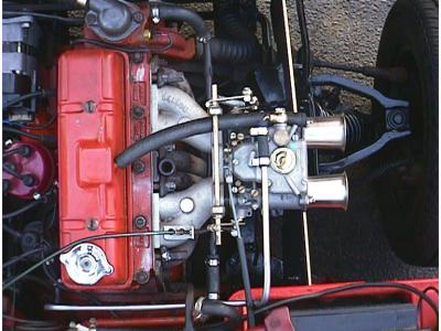
Yep! It's sitting on a Cannon manifold. When I got it home I did some
tweaking by the book. As usual, the P.O. must not have truly known what they were doing. I
was able to get the idle down to 850-950 rpm and still remain relatively smooth
(considering the cam in it.)
I adjusted the valves just for my own peace of mind. So I would know what the clearances were set to. That's when I noticed the head. HHMMmmm.. I know '78's had an air injector system and that it's been removed on this car..... but this head doesn't even have any ports! I also noticed thicker copper lower spring collars and double springs. Correct me if I'm wrong, but the double springs were a European standard, not US. So I guess the P.O. setup up this configuration when he installed the high lift cam. Also the engine serial number has an 'SS' suffix. I have come to find that this means the engine was a 'factory Supplied Spare', and or 'Special Systems' depending on who you ask.
I use a micrometer depth gauge on a magnetic base to see that the valve is full depressed before adjusting the appropriate valve. I noted then, that this Kent cam lifts the valves 0.340" (stock is somewhere around 0.240") Duration?? Cam timing?? Who knows. The timing chain cover doesn't leak so I'm not going to pop it off just to check it...that is for now anyway.
![]()
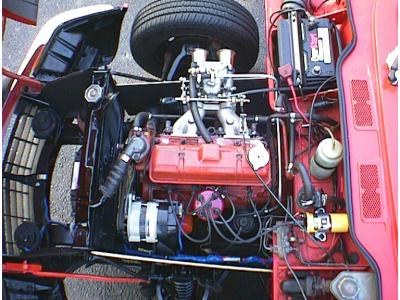
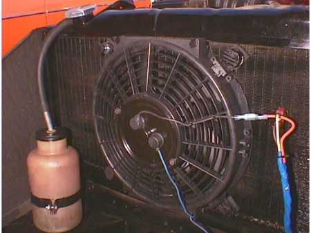
Common knowledge to anyone who regularly rev's a 1500 with the 8 blade large center hub 'clutched' fan, is the idea of the fan's propensity to lodge itself in the radiator. Sooner or later it WILL happen to you! Let's face it. The viscous clutch design sucked. This Spit was also the victim of those faulty clutch bearings. Hence, quite a few radiator core elements were damaged when I purchased the vehicle. But this is a full width radiator. The P.O. had installed some unknown after market electric fan in front of the radiator after loosing the old engine driven fan and clutch assembly. I replaced his fan with a new shrouded electric fan controlled by a thermostatic switch and relay. I trimmed down the outer casing of the fan to clear the top and bottom tanks which let the fan frame rest firmly up against the fins. This will guarantee maximum air flow through the radiator, not out past the sides of the fan. It is a spring loaded mount system. Actually turned out quite nice. Notice in the following photo, the fan is off-center. I placed it in front of the majority of elements left undamaged by the fan.
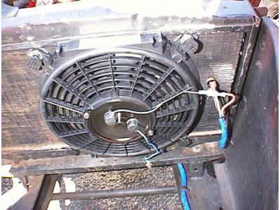
(photo before the re-painting)
The thermo switch (165°C) is the little 'do-hicky'
to the right of the main fan body. It has a probe stuck through the fins for maximum
contact. The squared-off top and bottom edges of the fan are what I cut up to clear the
tanks, and recess the fan closer to the fins. The blue you can see at the bottom of the
photo, is the wiring harness that I completely re-wrapped, al the way back up to the
firewall. All added and stock wiring was re-routed and wrapped in the original harness.
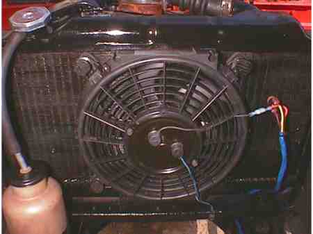
Well the damaged radiator (that came with the car) was replaced with a used one in great condition I picked up from a fellow list member. A little scrubbing, wire brushing and a light coat of high heat paint, and it looks brand new. A 14psi pressure radiator cap has already proven to me that this radiator is in superb shape. Being a full width unit (21" core) I shouldn't have any cooling problems ever. I also re-installed an over-flow bottle to keep it clean.
----------------------------------------------
![]()
Well I got quite a few questions from the Spitfire E-mail List
Group, so I guess I'll post the following pictures and explain myself a little.
I didn't like the idea of running without an air filter. (Been there...done
that....regretted it!)
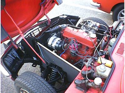
As purchased, the Weber DCOE had 60 mm (~2.5") long ram
stacks. (all the above photos) This barely gave me 3/8" of clearance with inner
fender well wall when opening and closing the bonnet.
I removed the 60's and installed 26 mm (~1.0") ram pipes and
added a 2" thick oval K&N Filter. I now have an extra 1/2" of clearance as
compared to before, between the fender and the air cleaner.
new K&N Filter with 26mm ram stacks inside
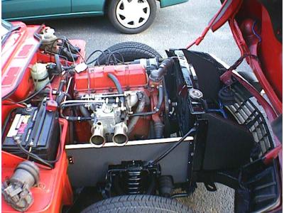
I punched a hole in the top of the K&N Filter and installed a generic PVC valve routed back to the valve cover. At least the crank fumes will get burned rather than venting straight to the atmosphere.
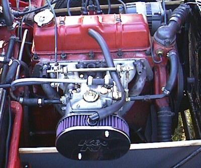
off-the-shelf PVC valve connects my valve cover back into the air stream
![]()
A 'stock' configuration exhaust system, but large bore and stainless steel, fed by a cheapo header. Check out what an hours work polishing the tail pipe looks like! You can see the abrupt transition back to the unpolished area. That's a 2" tail pipe! Nice powerful mellow tone when you get on it, and it's not the least bit buzzy or loud.
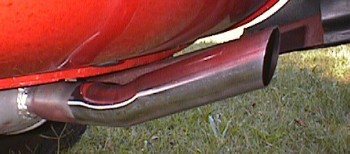
polished stainless steel tip. Polished by me!
****** Update 10/99 ******
That stock muffler had to go! I beleive it's simply creating too much back pressure. So I'm going to go back to the single 'Cherry Bomb' muffler, but I'm adding a Monza Chromed Dual tip resonator to the tail end.
...........pictures to come.
****** Update 11/99 ******
...sitting in the wings, waiting to go in, is a very good condition Overdrive transmission I just aquired. But that will have to wait until the Midget is done.
****** Update xx/99 ******
--------------------------------------------------------------
![]()
copyright![]() 1999
1999 ![]()
![]()
![]()
accesses