|
|
|
||||||||
|
|
|
||||||||
Emissions and Cranckcase Ventilation Issues |
|||||
|
|||||
|
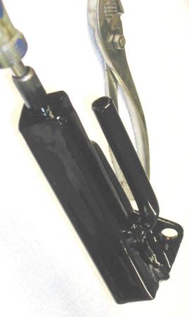
| My second design was geared
more towards larger breather pipes, and attempting to control which pipe had how much flow
and pressure in it. This unit was made up of sqaure tube stock with multiple holes
drilled in it. The idea was to direct the pressure from the rocker cover pipe, to the
crankcase, and then pull air out another port, (pulling equally on both vents) and
connected back directly to the intake manifold to maintain a vacuum in the crankcase at
all times.
|
|
|
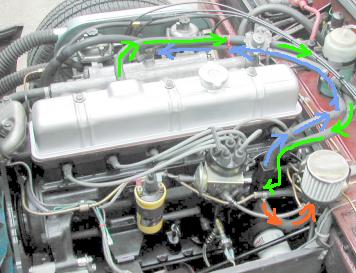
This unit had a small verticle square pipe up the back that attached the larger second pipe, the screw driver handle is stuck down through (photo at left). The 'forward' tube is the seperator chamber in this design. The rocker cover vent pipe feeds into the pipe that sticks into the side (in front of the plier handles) of the rear box/tube. This model unit worked well with the flow patterns as shown by the arrows in the next photo below, but....
The green arrows show the air pressure flowing out of the rocker and into the side of the breather box. The blue arrows, show the high vaccum direct manifold tap. The red arrow show a secondary breather filter, incase the crankcase were to 'push' more air than the vaccum pipe could 'pull'. The filter line has a PCV valve in it so the vacuum can not pull air in through it, but crank pressure could/can blow as needed. |
|
|
| I mentioned this setup worked, but....
What I mean is the pressure was reduced in the upper rocker cover, but
I was still blowing oil out the rear lower crank rear seal. It was also hard to get the
idle stable or the wide-band oxygen meter to read steady. And man! did this setup ever
gunk up the intake! It was sucking oil into the intake big time!
|
|
|
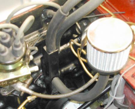
A secondary 'output' filter was added to this version. The filter. Again, the goal here is zero pressure build up in the crankcase. So I added a bracket under the edge of the brake differential switch on the bilkhead and mount he filter there. |
|
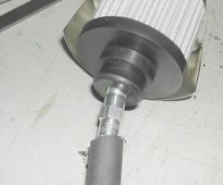
I installed an off-the-shelf PCV valve in the bottom of the filter. This was the largest i.d. PCV valve I could find and fit nicely into the hose as well as the bottom of the filter. |
Emissions and Cranckcase Ventilation Issues |
|||||
|
|||||
|
![]()
©1987-2010
All material copyright© Teglerizer 1996-2008last edited
3/15/08

hits since last reset


index