|
|
|
||||||||
|
|
|
||||||||
Emissions and Cranckcase Ventilation Issues |
|||||
|
|||||
|
| A combination of all the
development and testing to date, has led to what configuration I'm running right now. As
of the time of this write up, (6/21003) I can only imagine
one more detail to cover, other than the system as currently installed and described here.
That will be described later.
|
|
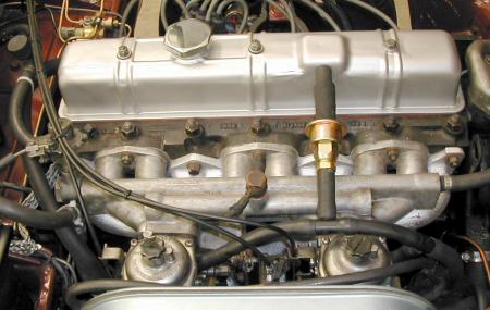
| In the shot above
you can see the 5/8" scavenging hose coming up from under the left side of the left
carb. It routes behind/under the interior heater control valve and plumbing, and then
curves back around to the right, behind the valve cover. The second one way valve (from the Moroso kit) was added in place of the straight through hose that would have originally connected the rocker cover to the carbs and emission canister. Since the exhaust is sucking on the bottom end of the motor.... at high speeds, I didn't want the rocker cover to possibly pull a vacuum on the carb ports. |
|
|
|
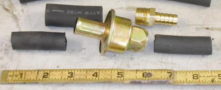
The connection was made up using a hardware store supplied, brass 1/2" hose i.d. to 7/8" threaded adapter (top right in photo). The valve is standard pipe threads (as is the little weld in pipe) A piece of 1/2" i.d. radiator hose was jammed inside a 5/8" piece of hose. The 5/8" fits the valve body. When the 1/2" i.d. end is stuffed onto the rocker cover outlet, it tightens it up nicely inside the 5/8" hose. So no clamps are needed for a nice air tight seal. In essence, this works as a standard PCV valve, but has a full 1/2"-5/8" diameter breathing passage as compared to an off-the-shelf 1/8" to 1/4" of most smaller standard size PCV valves. |
|
I ended up making up a fifth breather /separator adapter for the crankcase connection at the fuel pump. Again, a Mr. Gasket blanking plate was used as a base. A piece of square stock was rounded out to match the rubber grommet supplied in the kit for the base of the breather/filter. This allows me to 'push-in' the breather filter, just like the original breather kit design was suppose to allow for. |
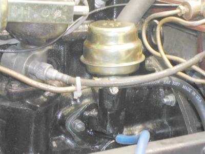 |
The gold dome, has a filter media built in as well as baffles to separate the oil from the air stream. This is a standard style big american V8 valve cover breather, and is supplied as part of the Moroso scavenging kit. (x2) The blue vacuum line in the photo at above, is attached to the extra oil return feed line on this fifth model. In this photo the oil return port is is being used as a pressure/vacuum gauge port. This allowed me to see what the crankcase pressure was doing while I drove it around the block. The 'added' feature, as mentioned
at the beginning of the page...
|
|
...... update 7/2003 ......
|
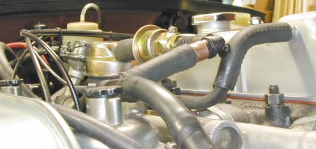
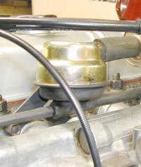 The rear hose barb is an oil drain out for anything that accumilated here in the upper separator. |
Well I've added 'my version' of an oil/air separator between the PCV valve and the rocker cover. This should keep the PCV valve and intake free of oil. This 'custom' separator was made from the second separator included in the Moroso kit, a short length of copper 1/2" diameter tubing and a threaded hose barb. I simply squared up the bottom large i.d. opening of the breather/separator and soldered in the copper tube and hose barb. Hose barb? Yes. It's used as the 'end' of the tube and the drain tube for any accumulated oil in the breather. This is visible in the upper right photo. A small tube feeds the oil back down to the crankcase breather. One end of the plastic 90 degree angle was filed off and stuffed (in a vise) into the end of a 1/2" to 5/8" brass piping adapter. This acted as the reducer needed to match tubings at the carbs and PCV valve. The hose adapter barbed end is simply stuffed inside the other end of the plastic angle adapter. |
|
The rubber tube exiting the rocker
cover curves down, and flows back to the separator. The 'down curve' is smooth, as the
copper pipe from the separator runs all the way up inside it to the very edge of the
rocker cover nipple. |
|
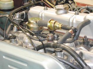
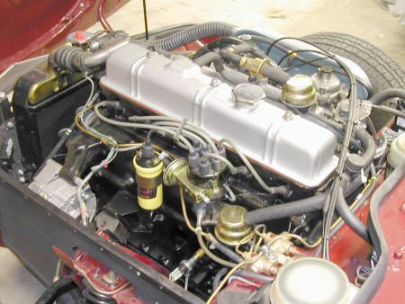
This shot shows the whole system (almost). You can see the crankcase breather/separator (behind/below the distributor) and large hose headed for the exhaust scavenging PCV valve. To the right of the top oil filler cap (hex shaped here) you can see the upper PCV valve and separator. The oil return line from the upper separator going to the lower crankcase vent assembly, can be seen routed between the brake pressure differential switch block and the master cylinder on the bulkhead. |
|
Current Consensus...
I happen to own gauges that allowed me to directly measure the actual SCFH (cubic feet per hour) flow rates the crankcase and rocker cover vents wanted to breath. I was also able to measure the suction volume of the scavenging system as well. I wanted to independently know the functional limits of each of these sub-system breathing pathes. As well as path pressures, I was able to track the effects of all this 'emissions' changes on the air/fuel ratio as different 'sources' or 'pathes' were made available or dis-connected. On my own installation, a 1973 MKIII GT6 1998cc 6 cylinder engine. |
|||||
| Scavenge port 'pull' @ 1.0 psi pressure drop |
Rocker cover vent output w/ Manifold Vacuum applied to Crankcase vent poor idle, no power, |
Rocker vent output w/ crank vent closed | Rocker vent output w/ crank vent being scavenged |
||
| 850 rpm (idle) | 35 SCFH | 5 SCFH | 40 SCFH | 2 SCFH | |
| 1 krpm | 60 SCFH | 10 SCFH | 60 SCFH | 2 SCFH | |
| 3 krpm | 80 SCFH | 25 SCFH | 90 SCFH | 5 SCFH | |
| 6 krpm | 120 SCFH | 50 SCFH | 170 SCFH | 12 SCFH | |
| By
'specs' the 1998cc Triumph 6 engine, kicking out 100hp, should be blowing about 2.5 cfm, . (cubic feet / minute) or 150 SCFH) |
|||||
Emissions and Cranckcase Ventilation Issues |
|||||
|
|||||
|
![]()
©1987-2010
All material copyright© Teglerizer 1996-2008last edited
3/15/08

hits since last reset


index