|
|
|
||||||||
|
|
|
||||||||
Whitey - A 1975 Spitfire 6 Cylinder and Fuel Injected Conversion |
||||||||||
|
||||||||||
|
||||||||||
|
||||||||||
|
||||||||||
|
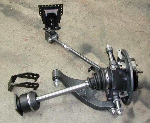
| Well it's been awhile since FIS6 has seen any new work. I decided it was time to upgrade the rear suspension. Although the swing axles had already been converted to the larger GT6 rear self adjusting brakes, I decided to go the full independent rear suspension route.
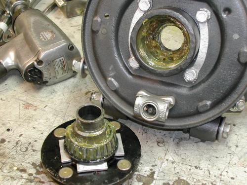
So of course ...EBay to the rescue ... supplying me with a complete roto-flex setup. BUT ...I knew I did not want to use the big donuts due to a variety of the normal reasons (maintenance, repair cycle, etc) I went into this with the full intent of going with a full CV jointed axle setup. I also needed all the mounts associated with the GT6 roto-flex setup as this was a '75 Spitfire adaptation. In the following picture you can see the knee wall mount (top center) already punched around the parameter and ready for welding into place. Also I'd need the frame mount bracket for the lower a-arm. The CV jointed axle assembly is hub to hub from Canley Classics out of the U.K. (as were the two needed brackets.
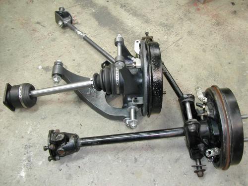
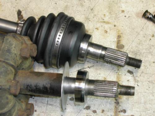
The upright and stock lower a-arm were sand blasted and powder coated. I disassembled the CV axles, painted the hubs flat black and clear coated the shiny axle (so it would hopefully stay that way). The next shot is just a photo comparison of the old and new axle set up. Even though the axle is Whitey's original 1975 axle upright and bearing block, the wheel drum, back plate and brake innards are the larger self adjusting late MKIII GT6 units.
Note carefully the CV axle setup brake back plate. I added an L bracket to the back plate like the Spit back plate to support the hard brake to flex line setup of the Spitfire. I routed the hard line around the bottom like the swing axle setup rather then simply up to the bracket and out along the trailing arm like a stock roto GT6 would have been. This way I did not have to completely alter the hard line routings on the Spitfire frame. (even though I did change them around quite a bit...but for other reasons) After a few questions, I've come to find the Canley CV assemblies are not all totally 'new'. Actually the outer hub and main axle are from NOS stock from the 60's/70s from a front wheel drive vehicle Triumph once built (special duty) Only the inner hub is made 'new' to match the current diff stub axle flange. While waiting for them to arrive, I'd removed the seal ring from the old roto-flex axle and polished it thinking I'd need it for the new axles. Wrong! They are built into the hub. I went ahead and polished the surface now which should help the seal last longer.
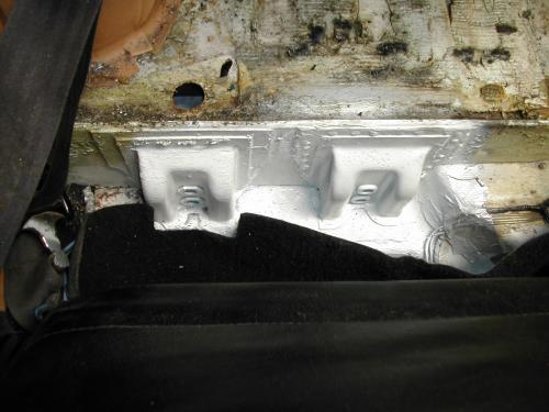
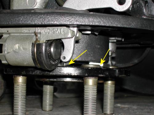
Since the Spitfire has the trailing arm brackets mounted more outboard, I needed to add/move them inboard to mount the GT6 arms correctly. In my case, I simply ordered up a spare set and welded them in over the holes in the knee wall that are already there. (just filled with little rubber plugs on the square tail spit) So now FIS6 has these strengthening mounts in BOTH locations. (The one at the right is the one I just added in the following picture)
Many people think this difference of position had something to do with tire clearance issues. Actually, this inboard location puts the trailing arm inner pivot in line with the lower a-arm frame mounted pivot point. So in essence, the combo of lower a-arm and trailing arm becomes one large triangulated a-arm assembly and articulates as such. There are already a couple of sites out there showing how to assemble the hubs. So I'll only add this one trick I learned for getting the outer seal seated since it's captive behind the outer bearing after the bearing is pressed onto the hub. In the following picture you can see I've place four small 1/8" thick slivers of aluminum between the hub and seal. These keep the seal pressed tight against the bearing. So when the hub is inserted into the upright and pressed into the inner bearing, the seal is seated home in the upright. Then the strips are simply removed.
In this next shot you can see the slivers (yellow arrows)... as well as the up rated 1/2"-20 Rover FreeLander studs which match the knurling and head design of the oem studs perfectly.
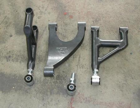
As always....and you all know it now ...I can't leave well enough alone. I don't need the big curve in the oem lower a-arm as I did not need to clear the roto donut with these CV axles. Plus I wanted to add an adjustability to the arm to allow for setting chamber. I didn't want to cut up a good set of lower arms so I built a set from scratch.
The inner end of these new arms are 'Mr. Roadster' ends designed for Hot Rodders to build 4-link rear suspension arms. Heim joints to me just don't belong on road cars. These nylon bushed ends are forged steel. (They are also avail in investment cast Stainless Steel...surprisingly inexpensive to boot!) The arms are made of 1" id. thick wall DOM tubing. They are really only about 50% lighter than stock because the threaded bung welded into the end of the tube for the rod end is a massive chunk of metal. The outer od. is roughly 1-3/8" diam. and about 2" long. The threaded portion is 5/8"-18 with a matching lock nut. As designed, I can adjust the camber from +/-5 degrees, regardless of which of the three frame mounted flange holes I chose to use. That's much more range then I'll ever need while still being able to maintain a sizable portion the thread engaged in the arm bung. The bearing through hole is 1/2" (avail in 9/16 as well) As the width of the end is slightly shorter than the stock a-arm width, I'll just stack a few washers beside it in the frame flange. A design feature there.... it assists in setting toe in/out in unison with the trailing arm. So I can center the wheel in the wheel well and align it with the spring, and adjust the washers to change toe in/out....more on that in another picture below......
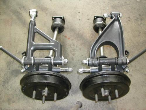
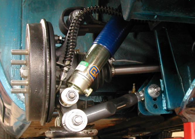
Here's a shot of the custom arm (on the left) vs the stock lower arm (on the right) The stock arm is currently assembled with poly bushes at the a-arm/upright interface. But I decided to go with oem nylon bush/trunnions to minimize compliance here (as pictured on the new arm above). I also added grease zerks for the bushes, just visible as little gold colored nubs sticking straight out towards the brake drum in between the oem bushes on the new arm set up. OK.... all mounted up with new GAZ shocks to boot! BUT ...I may have to take it apart again :-( I'd added a couple of those nylon buttons to the spring when the swing axles were still there. The roto set up with the same spring sits MUCH higher as the upright does not lean in like the longer axle swing axle setup does. Yes...the one drawback...this setup (roto or CV) looses 2" of track width. The CV (roto) setup is the width of the older shorter swing axles. So I'll probably pull this so I can remove a button or two as needed to set my tail back down where I had it before.
Here you can see the Spitfire style flex line interface a bit better than before. Those are stainless steel flex lines, but I like using the old protector coils on the lines just to help minimize possible chaffing of the flex line. Here you can also (just barely) see the tips of the grease zerks sticking out the ends in line with the main a-arm tubes) The last shot here shows the washers and inner bush end pretty well. One side has all three washers on one side, while the other side of the car has two on one and one on the other side to set toe-in.
So...is that real 'adjustment' requirements.... or my lack of real accuracy in
constructing these a-arms :-)
|
|
|
![]()
©1987-2010
All material copyright© Teglerizer 1996-2008last edited
3/15/08

hits since last reset