|
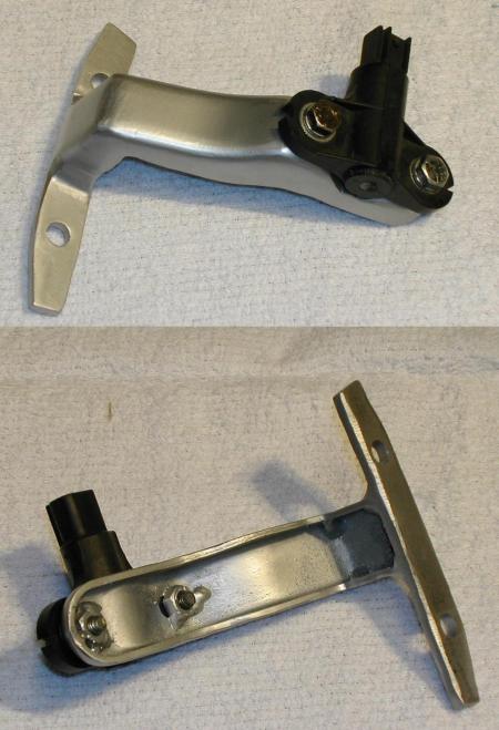
This was a hard one. How do you add a very rigid mount for a VR sensor, when there isn't much room to mount one to begin with. How do you mount a 35-1 trigger wheel, without custom making the wheel itself. Ok...what do
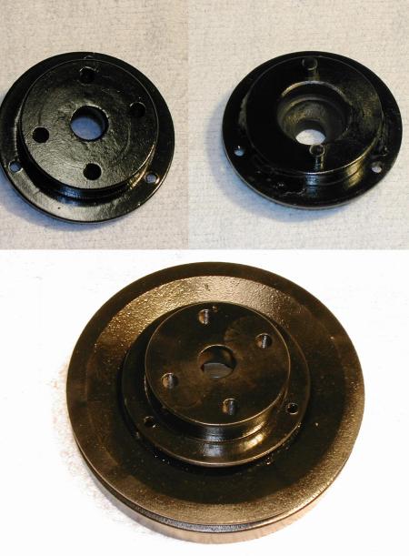
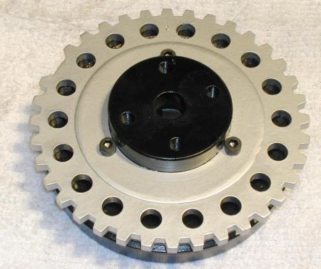
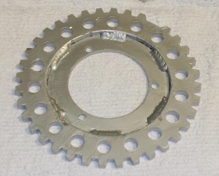
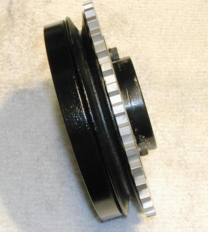
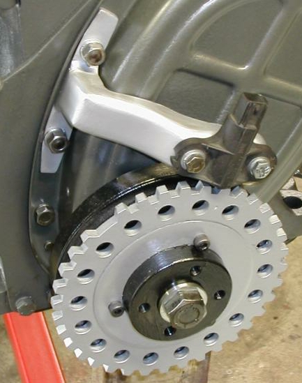
I have on the shelf here. Hmmmm... Got it! Ok... a simple 'V' cut in both sides, fold it, cut it to length, a bit of welding, a little grinding for looks. Yeah, that's the ticket. The 'tang' with the two holes simply bolts up with two bolts that hold the front timing cover on. As usual, everything as 'cut-to-fit' tack welded in place, then removed, welded up, ground and cleaned up, then painted and installed on the car. The trigger wheel was tricky, but turned out ultra simple in the end. Two donuts were cut. One fits perfectly around the fan extension and was welded in place. The other fits the Ford 'off the shelf' trigger wheel. Once the sensor was mounted, the wheel position was determined per the standard Megasquirt 6 cylinder EDIS instructions, then three holes were drilled and tapped, to fix the wheels position relative to TDC.
...update 3/12/06
Well I got it all mounted up today after some fresh paint and all new seals. The pulley went on first. Then I installed the sensor arm and put a 1mm spacer between the sensor and wheel before tightening up the two mount nuts. So when everything was tightened up, I have the proper (best?) clearance for this particular sensor and wheel setup. |